


Few WW2 era aircraft raise as much contradictory discussion as the Mitsubishi Zero; in the first year of service it gained a “Myth of Invincibility” that was eventually torn down, resulting in a disregarding of the aircraft's capabilities owing to the fact that it stuck around for longer than it should have. Behind the legend however, it is often overlooked just how good this aircraft was; after all, an object does not earn such an accolade as “Invincible” by being merely average.
Jiro Horikoshisan's design for a Type '0' Carrier Fighter was original in execution and contrary to popular belief, owed little to foreign influence; it met the demanding requirements of the 12 Shi specification owing to an innovative structural design that was entirely modern and unique in an aircraft of its era. In order to meet the criteria, Horikoshi realised that weight saving was the key to his fighter's success and a newly developed aluminium alloy was used in its construction, commonly known as Extra Super Duralumin, which, like today's 7075 aluminium alloy had zinc as the largest alloying element.
Structurally, the Zero was designed for ease of construction and maintenance, with lightness at its core; the centre fuselage incorporating the cockpit was rivetted directly onto the wing centre. Just aft of the cockpit the rear fuselage unit was bolted on as a seperate structure. This enabled the aircraft to be broken down into easily transportable components. A novel aspect of the design for its time was the absense of a turtle back aft of the cockpit; it sat as a three piece unit atop the fuselage, allowing unrestricted visibility in almost all directions. Drag reduction measures were extensively undertaken to improve the aircraft's performance; the entire exterior structure was flush rivetted and all excrescences were designed to fold away flush with the exterior skin.
When it first flew on 1 April 1939, the Zero was unmatched in performance among carrier based aircraft. After astonishing demonstrations of its endurance in the first year of the Pacific War its reputation was secure; there was no other fighter in the world that could carry out the missions its pilots did.
The Zero was however, ultimately a victim of its own success, as a determined enemy such as the Americans was always going to find a flaw and exploit it; the weight saving concept that was the design's raison d'etre was considered a weakness to the Allies, and was savagely exploited. In truth however, despite more powerful and better armed Allied fighters appearing in greater numbers than what the Imperial Japanese Navy could field, the Zero's virtues remained unmatched; because of its manoeuvrability at low speeds and low to medium altitudes it was a formidable adversary for the rest of the war and was never to be tangled with in a dog fight.
There has been some debate as to the structural strength of the aircraft, bearing in mind the proliferation of litening holes in as much structural support members as possible, even in the pilot's seat, but despite being lightly built, the integrity of the aeroplane was far from weak. The following was written by John Foster Jr., Managing Editor of “Aviation” magazine in an article describing the A6M3-32 in depth;
“This weight saving design would indicate that the craft is flimsily built, but such is not the case, for its strength compares favorably with many American built planes.”
Two different aircraft are used in this study; airworthy A6M3 c/n 3869, recovered from Babo airfield, Irian Jaya in 1991 and A6M3-22 c/n 3835 (although it is fitted with the rear fuselage of c/n 3844) acquired after surrender by the Royal New Zealand Air Force at Kara airstrip in southern Bouganville in 1945. The photographs of both these aircraft were taken in New Zealand; 3835 survives at the Auckland War Memorial Museum and 3869 was shipped to New Zealand especially for the 2010 Warbirds over Wanaka airshow, although a refuelling stop at RNZAF Base Woodbourne, near Blenheim enabled me to get close to it.
C/n 3869.

C/n 3835 today and how it appeared when it first went on display in the Auckland museum wearing a spurious colour scheme applied by the RNZAF.


C/n 3869 from different angles, highlighting the aircraft's svelte lines.

The Zero's wing comprised two spars of continuous 'I' sections that ran from tip to tip and were made up of two 'T' section extruded caps mated by a solid vertical web. The outer face of each spar was milled to sit flush with the outer wing skin.

Wing profile was designated Mitsubishi 118 and had a similar mean camber line to the NACA 23012 aerofoil that had been used in the Zero's predecessor, the A5M from the same design team; it was also used on the twin engined G4M land based bomber. Considerable care went into providing as clean a surface as possible. Underwing tie-down points are concealed by flush covers and spring loaded hand-hold plates sit flush with the surface when closed.

At the wing root the profile was NACA 2315 and the wingtip profile was NACA 3309. Washout was incorporated at the wingtips, which gave the Zero a comparatively low stalling speed. The Zero's centre of gravity was 0.075 inches forward of the main spar.

The fuselage breaks at a point just forward of the Hinomaru, where the aft fuselage attaches to the wing and fuselage centre section, which is rivetted directly onto the wing top surface, proving integral strength as a single unit. The top surface of the wing serves as the cockpit floor. The rear fuselage is a full monocoque and comprises a single keel longeron running its length and 22 'Z' section stringers supporting the frames, which are extensively lightened by litening holes around their circumference.

The after equipment bay was located directly behind the cockpit and the only access to this was by tilting the pilot's seat forward. Oxygen bottles and radio equipment was located in this section. The aircraft wears the markings of an A6M2 based at Kara, with the Commemorative Air Force Wings visible on the fin.

Stabilisers were two spar units with leading edges held in place by piano hinges. Control surfaces were aluminium framed and covered in fabric. The fin was built integrally with the rear fuselage. The elevators are fitted with in-flight adjustable trim tabs, whilst the ailerons and rudder has ground adjustable tabs only.

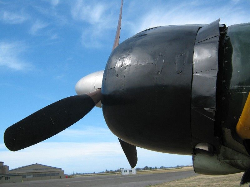
The Zero's Sumitomo Constant Speed prop was 10 ft 3 inches in diameter and was similar in design to the Hamilton Standard constant speed counterweight propeller. It was fitted with a fluid slinger ring for de-icing the blades. Intake up top of the cowl is for a two stage supercharger on A6M3 model. 3869 is powered by an R-1830 Twin Wasp as in your average DC-3/C-47, I suspect the prop is a Hamilton Standard unit, but what type I'm uncertain. The DC-3 is fitted with the 23E50 Hydromatic prop.

A6M3 is nominally powered by a 14 cyl Nakajima NK1F Sakae 21 of 1,130 hp. A6M2 a Nakajima NK1C Sakae of 940 hp. Bore is 5.12 in, stroke, 5.91 in, displacement 1,700 cu in. With an outside diameter of 45 inches, the engine was carefully cowled for drag reduction. The cowl comprises two easily removeable sections split horizontally, the oval plates concealing the release latches for opening the cowls for maintenance. The cowl flaps are manually operated.
More soon.


